


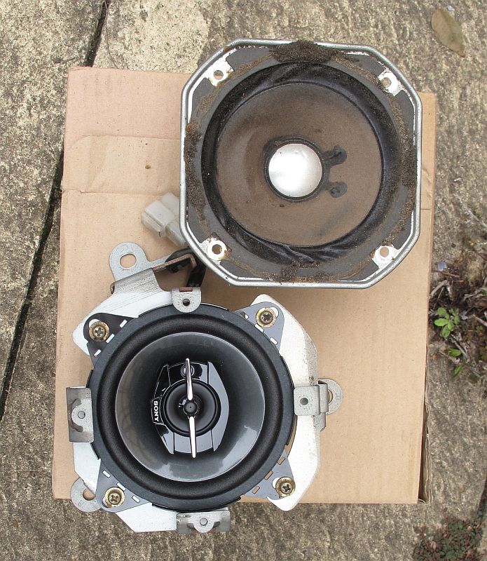
Wanted to keep the old technics speakers, but they were too far gone. Replaced with Sonys.
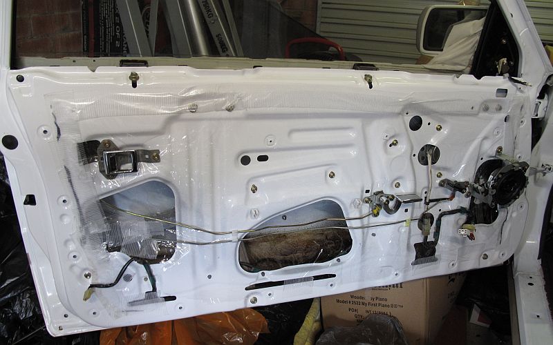
Passenger side door prepared, with handles and lock connections installed.

Driver side door prepared, with handles and lock connections installed.

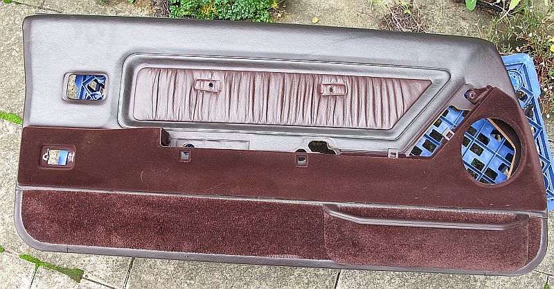
Door-card cleaned with Connoly Hide care. Ready to be installed.

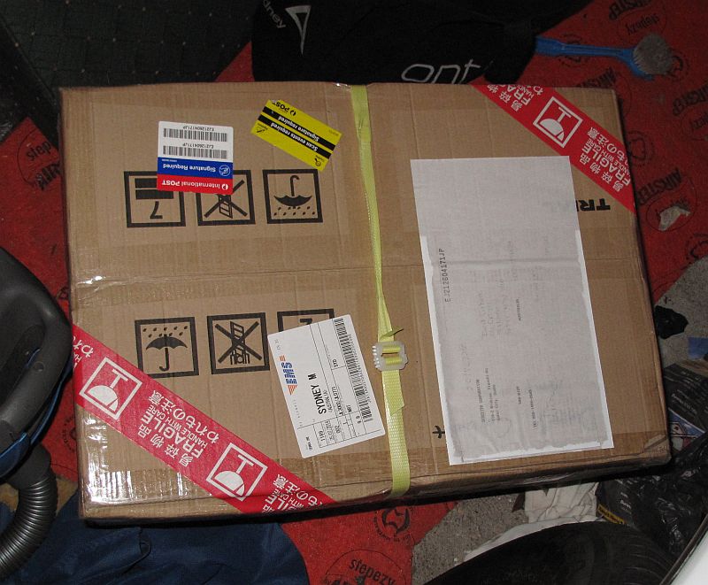
EMV Box arrives!
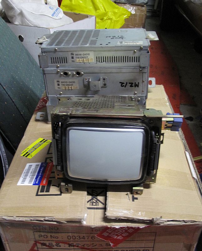
EMV box contents.
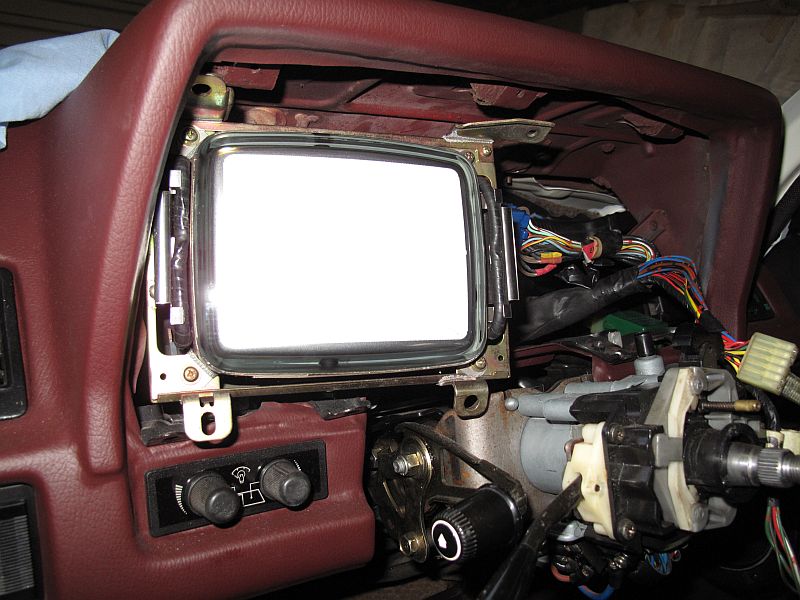
EMV in dash for testing!
Video from the phone is not the greatest, but it works!!

Info:
http://books.google.com.au/books?id=53nnX4fnnNIC&pg=PA220&lpg=PA220&dq=b-y%2C+r-y%2C+g-y+chroma&source=bl&ots=1udP3jnpaL&sig=rntO3MGxEeoK2435_mruSWo6zhs&hl=en&sa=X&ei=qFxzU_LKLIyPlQWxt4DwCw&ved=0CCgQ6AEwAA#v=onepage&q=b-y%2C%20r-y%2C%20g-y%20chroma&f=false
There seems to be 2 circuit paths:
One that takes R-Y, B-Y, G-Y and Y and then matrices the Y into the R-Y, B-Y, G-Y. This is done apparently so that the amount of Y added can be adjusted per colour. The output of this circuit goes into the R, G, B pins on the electrode gun. There are two more pins for earth and a heater?
The other takes the Sync and Power. There appear to be 3 syncs. SY, DH, DV. These are used to control the CRT deflectors.
So...
Feeding RGB + Ground from the CRT circuit and SY from the Input into the RGBS input of the converter produced no result. But I could have ruined up the CRT circuit when I was removing it.
EMV Computers: http://mz12gt.com/?p=293
Plan:
EMV Signal -> Converter Box -> ALR-1400 Controller -> 5.7" TFT
Parts:
Signal Interpreter: www.arcadespareparts.com/arcade_parts/video_converter/rgb_jamma_vga_converter_board/13052.html
ALR-1400 LCD Controller: http://www.digitalview.com/products/alr-1400-tech-specs
LCD Display: http://www.sharp.net.au/cms/articles/439/files/LQ057V3DG02%20LED%20BL%20%28TL%29.PDF

More Oscilloscope work.
The whole screen represents 20ms, divisions are 2ms Voltage divisions are 2V.
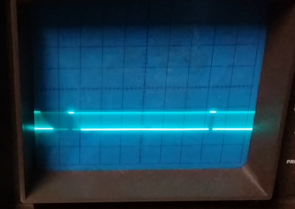
Oscilloscope output of the sync signal
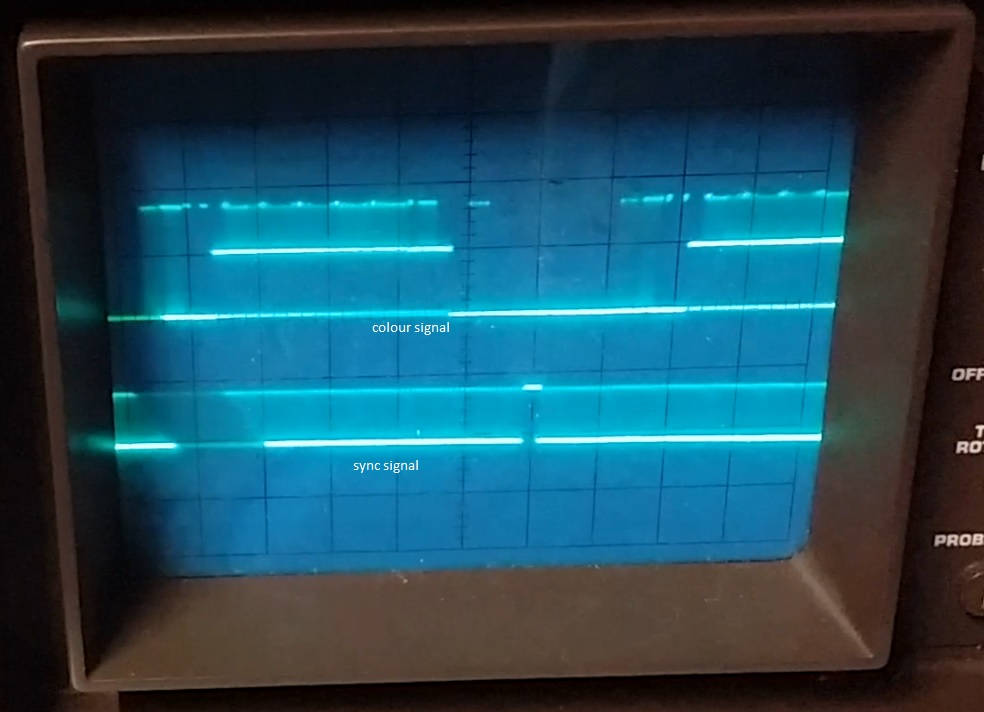
Oscilloscope output of the sync and colour signal
Links to videos.

Seems like the csync emitted by the EMV computer is either too noisey or not amplified enough for the upscaler board to get a lock on the signal.
To rectify this I have ordered:
- LM1881 eg. http://www.mmmonkey.co.uk/composite-sync-stripper-lm1881/
- EL4853 eg. http://shmups.system11.org/viewtopic.php?f=6&t=43992

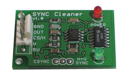
- JROK Sync Cleaner
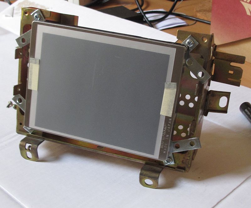
Also here is a test fit of the LCD I am using on the CRT mounting bracket.
Before

After

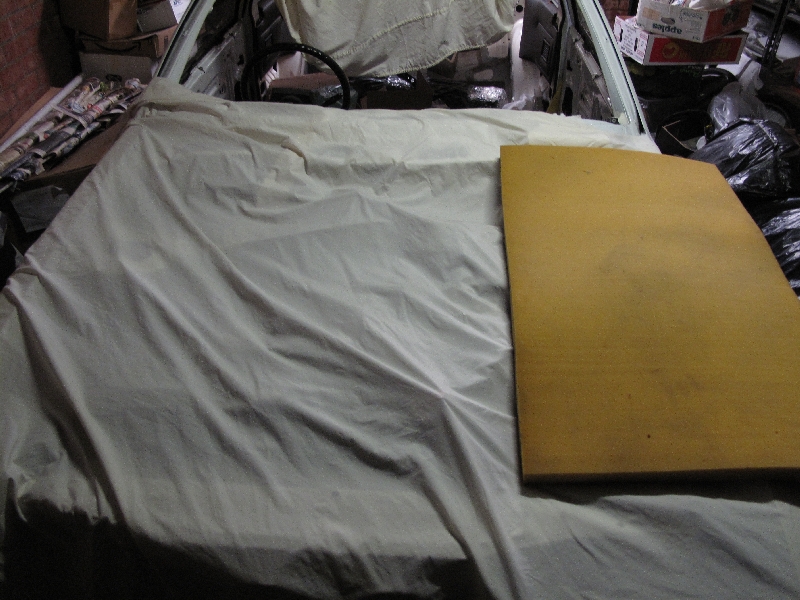
Under wraps.
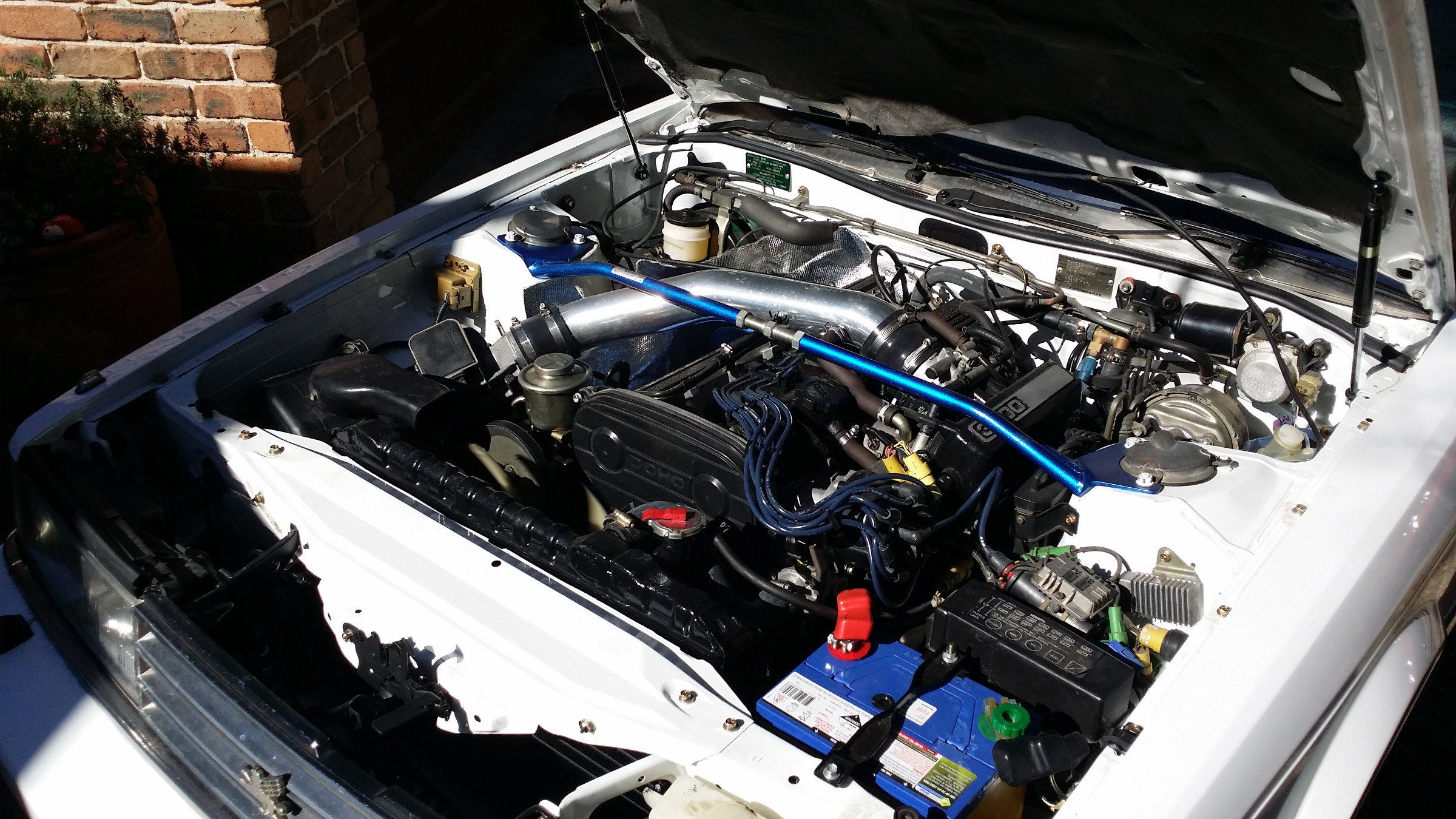
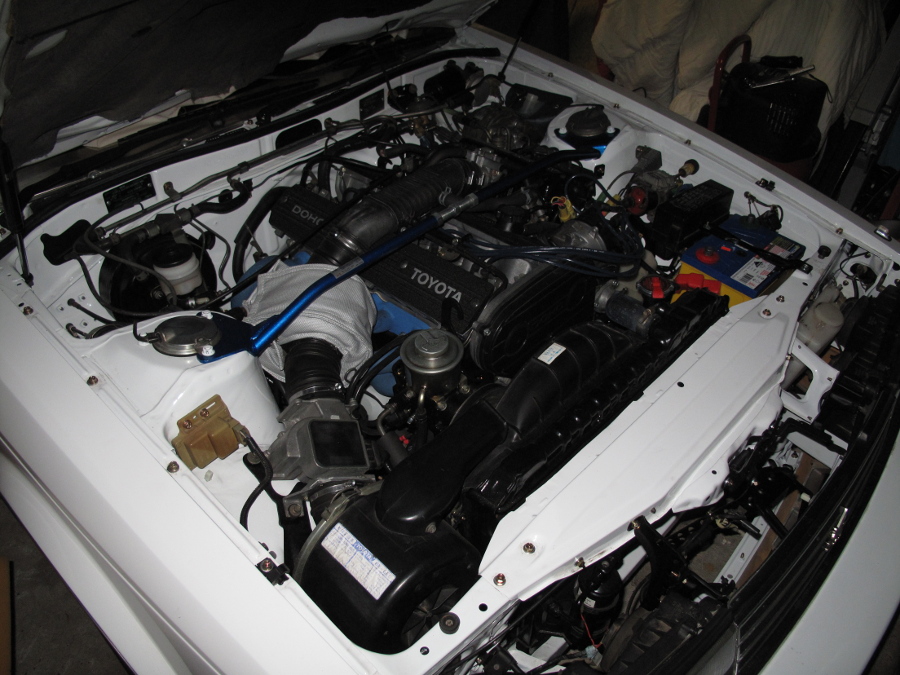
Progress.

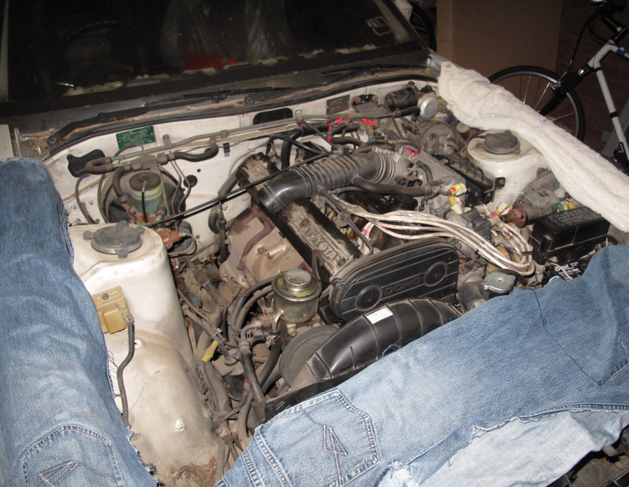
All that remains to do is start it.

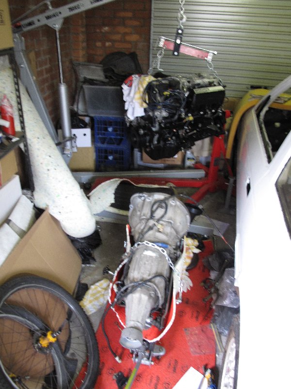
Freeing the engine from the engine stand.
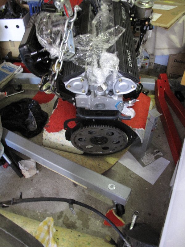
Flywheel attached, ready for the transmission
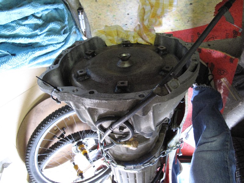
Torque converter installed. Takes ages to fill with ATF Dextron.
![]()
Transmission mounted to the engine.
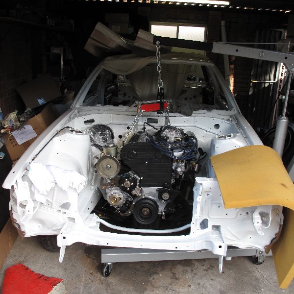
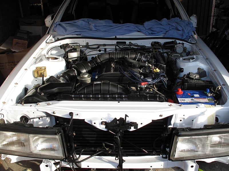
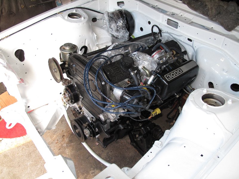
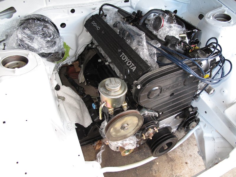
Trying to fit the engine into the car. This took hours.

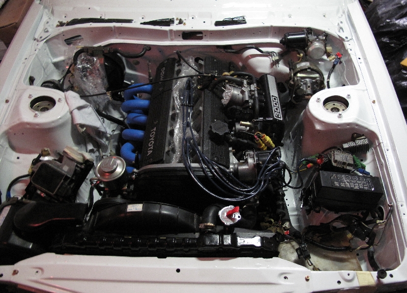
Success!
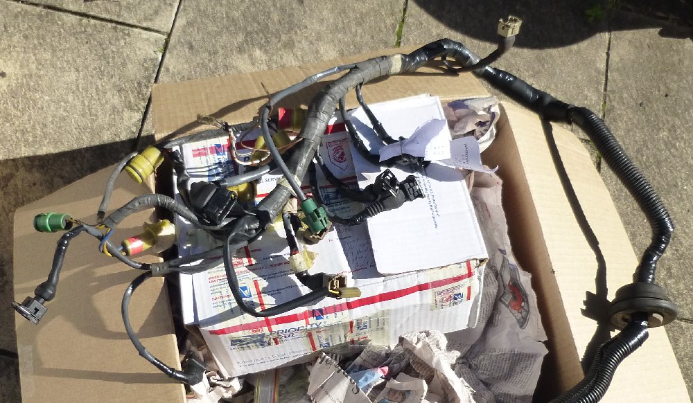
Rebuilt and installed the engine loom today. Replaced the old Denso connectors with GM ones.